Assembly turns a bare board and a pile of reels into a working circuit. Most parts today are surface-mount (SMT, surface-mount technology): they sit on pads on the board surface. Some parts, usually large connectors, transformers and power parts, have leads that go through holes (THT, through-hole technology). A board often has both, and the process has a step for each.
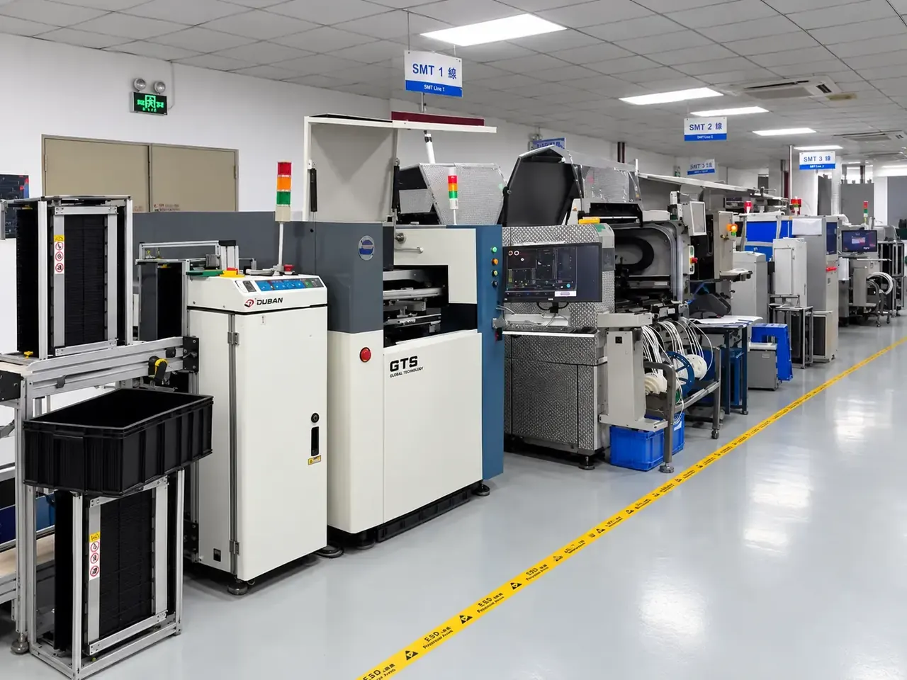
The line, one station after another.
- Printer: a squeegee pushes paste through the stencil onto the pads.
- Paste inspection: a camera checks the paste before parts are placed.
- Placement: a nozzle puts each part on the paste.
- Reflow oven: zones that heat the board, hold it, melt the solder and cool it.
- Optical inspection: a camera checks the soldered board.
1. Preparing the line
Before any board is made, the factory:
- checks that every part on the BOM is present and matches the part number,
- bakes moisture-sensitive parts that have been exposed too long (a plastic IC that absorbs moisture can crack when heated in reflow),
- loads the reels into feeders on the placement machine,
- makes or fetches a stencil, and
- loads the machine programs from your placement file.
What can go wrong: a wrong part in a feeder. This is why the first board is inspected closely (a first-article inspection) before the batch runs.
2. Solder paste printing
Solder paste is a mixture of tiny solder spheres and flux, with the consistency of toothpaste. The most common solder alloy for lead-free work is a tin-silver-copper alloy known as SAC305. A stencil, a thin metal sheet with holes where your pads are, is laid on the board. A squeegee pushes paste through the holes onto the pads.
What can go wrong: too much paste causes bridges between pads; too little gives weak joints or open joints. Stencil thickness, the size of the openings, and how well the stencil seals against the board decide the volume. Fine-pitch parts need a thinner stencil than large ones, which is why mixed boards are a compromise. Some factories use a solder paste inspection (SPI) machine to measure the paste volume on every pad before parts are placed. See Inspection and test.
3. Placement
A pick-and-place machine takes parts from the feeders with a vacuum nozzle, checks them with a camera, and places them on the paste, with its position set by your placement file and corrected using the fiducials, the small round marks on the board that the camera finds.
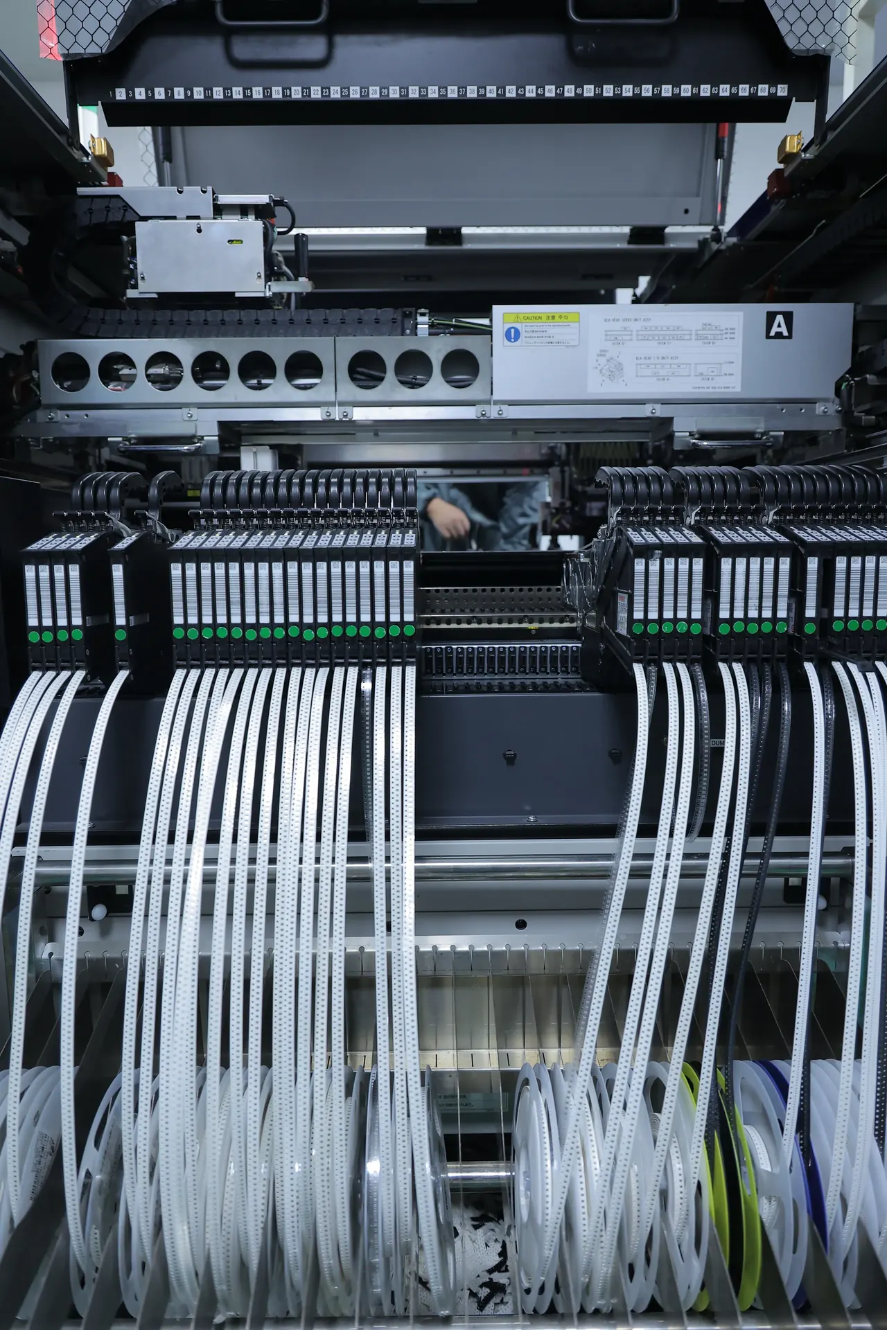
Small passive parts are placed very fast; large or odd-shaped parts, and fine-pitch ICs, are placed more slowly and more carefully. The paste is tacky enough to hold the parts in place until soldering.
What can go wrong: a part rotated 90 or 180 degrees because the footprint orientation in the library differs from the one in your placement file; a part missing because it ran out; a tombstone (below).
4. Reflow soldering
The board travels through a reflow oven on a conveyor. It passes through zones of rising temperature:
- Preheat: raises the board gently so that parts do not crack from thermal shock.
- Soak: equalises the temperature across the board and activates the flux.
- Reflow: the temperature rises above the melting point of the solder (about 217 to 220 °C for SAC305), usually peaking at about 240 to 250 °C for a short time. The solder melts, wets the pad and the part terminal, and surface tension pulls the part into alignment.
- Cooling: the solder freezes into a joint.
The profile, the temperature against time, is set for the board, its parts and the paste, and is checked with a thermocouple measurement on a test board.
- Preheat: a gentle rise.
- Soak: the temperature evens out and the flux activates.
- Reflow: above the melting point of the solder (the dashed line) for a short time.
- Peak: the highest temperature of the profile.
- Cooling: the solder freezes into a joint.
What can go wrong:
- Tombstoning: a small two-terminal part stands up on one end because one pad heats and wets before the other. Unequal pad sizes or an uneven copper connection to the pads are the usual causes.
- Solder bridges: from too much paste or pads too close.
- Voids: gas trapped in a joint, which matters under large thermal pads and BGAs.
- Head-in-pillow: a BGA ball that does not merge with its paste, often when the board or part warps during reflow.
- Parts shifting or falling: heavy parts on the second side can fall off during the second reflow if the pad area is too small for their weight.
- A good joint: the part lies flat and solder wets both pads.
- Tombstoning: one pad heated and wetted first, and pulled the part up on its end.
- A solder bridge: solder joins two neighbouring pads.
5. Second side
If both sides have parts, the board goes through the line twice. The side with the smaller and lighter parts normally goes first.
6. Through-hole parts
Through-hole parts are inserted by hand or machine, then soldered by one of:
- Wave soldering: the bottom of the board passes over a wave of molten solder. Fast for many pins. Surface-mount parts on the bottom side need to be glued or covered in a pallet to survive it. Our line uses a lead-free dual-wave process.
- Selective soldering: a small nozzle solders chosen joints one by one, without heating the rest of the board. Used when the board has parts on both sides, or heat-sensitive parts close to the through-hole.
- Hand soldering: by a trained operator for single parts, rework, and low volumes.
After wave or hand soldering, excess lead length is trimmed.
7. Cleaning
Flux residue left after soldering is harmless on many boards (a "no-clean" flux is designed for this). Boards for high voltage, high impedance or for coating are cleaned, for example in an ultrasonic bath, with a chemical suited to the flux. Ask for cleaning if the product is sensitive to residue.
8. Conformal coating
A thin protective polymer film (acrylic, silicone, polyurethane or other) can be sprayed or dipped onto the finished board, to protect it from moisture, salt, dust and chemicals. Connectors, test points and other areas that must stay uncoated are masked or avoided. Coating hides the board's surface, which makes inspection and later rework harder. Our factory applies coating selectively, by machine.
9. Programming and test
Microcontrollers and memories are loaded with firmware, either before placement or in circuit after soldering through a programming connector or test pads. A functional test checks that the board works. See Inspection and test.
Things to design for
- Equal pad sizes and symmetrical copper connections for small two-terminal parts, so they heat evenly.
- Fiducials on the board, and on the panel. See Panelisation and small boards.
- Space around parts for the nozzle, for inspection and for rework.
- Clear polarity and pin-1 marks.
- A choice of reflow-friendly parts: not all parts survive the oven, and a few (some connectors, electrolytic capacitors of certain types, batteries) must be added later.
How this shows up when you order here
Our factory has automatic solder-paste printing, 10-zone reflow ovens, high-speed placement, lead-free dual-wave soldering, hand rework stations and selective conformal coating. Which assembly options are available through the site, and their limits, are on the capabilities page. An engineer confirms every order and may ask about a part that cannot go through reflow, or a footprint that invites tombstoning. The 25 checks at upload look at the board files; they do not review your assembly for these process faults.