Assembly machines are built for boards of a certain size, and they handle small boards badly. A board of two centimetres is hard to hold on a conveyor, to print paste on, and to carry through an oven. The solution is panelisation: several boards are made as one panel, assembled together, and separated at the end. This article describes the options.
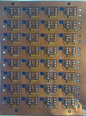
Who makes the panel
There are two views of panels. The factory builds boards on large production panels in fabrication; that is its own arrangement, and you do not see it. The assembly panel (also called an array) is what the assembly line handles, and it is part of your design. You can supply a finished panel, or you can supply the single board and ask the factory to panelise it. Both work. The advantage of supplying it yourself is that you control how the boards are separated and where the tabs are.
Parts of an assembly panel
- Boards in a grid, with a small gap or none between them.
- Rails: strips of board material along two opposite sides (and sometimes four). The machine's conveyor holds the panel by the rails. Rails of about 5 to 10 mm are common; the factory states the width it needs.
- Fiducials: small round copper marks that cameras use to find the exact position. A global pair of fiducials on the rails (and often a third) locates the panel. Local fiducials near fine-pitch parts locate a single board precisely.
- Tooling holes: unplated holes, commonly around 3 mm in diameter, in the rails. Pins in fixtures use them to hold the panel in place.
- Breakaway methods: V-cut grooves or routed tabs.
- Rails along the long sides: the conveyor holds the panel by them.
- A fiducial: a small copper mark the camera finds.
- A tooling hole, unplated, for the pins of a fixture.
- A V-cut line: the boards touch, and a groove runs along the dashed line.
- A routed gap with tabs; the holes across a tab are mouse bites, so that it snaps off.
V-cut (V-scoring)
A V-shaped groove is cut from both sides of the panel along straight lines, leaving a thin web of material in the middle. After assembly, the boards are snapped apart by hand or cut with a machine.
Good for:
- rectangular boards with straight edges that touch each other,
- the least wasted material,
- a clean, straight edge.
Limits:
- Only straight lines, across the whole panel.
- A very thin board cannot be scored well; a minimum thickness applies, so ask.
- Parts and copper must stay away from the groove: the blade cuts a little wider than the line, and the edge of the board must stay clear of copper. Tall parts near an edge can be hit by a cutting machine.
- Snapping boards by hand bends the board and the solder joints near the edge, which can crack ceramic capacitors (a common failure). Use a separating machine, or keep ceramic parts away from the edge.
Tab routing (and mouse bites)
The boards are routed out, with small tabs left to hold them in the panel. The tabs are often drilled with a row of small holes (called mouse bites or perforations) so that they snap off.
Good for:
- boards of any shape, with curves and corners,
- boards with parts that hang over the edge,
- thicker boards.
Limits:
- The router bit needs a gap between boards, usually about 2 mm, which uses up space.
- The tab leaves small stubs at the edge when it is broken, which may be rough. File or sand them if the edge must be smooth.
- Tabs should be placed where there is no copper and no part nearby, and where a stub does not interfere with the housing.
- Place at least two tabs per side that is held, enough to keep the board flat through the oven.
Some panels combine both: V-cut where the edges are straight, tabs for the others.
- The groove, cut from both faces.
- The web: the thin material left in the middle, which holds the boards together.
- Top view of a V-cut: the boards touch, and the groove runs along the dashed line.
- Top view of tab routing: a gap is routed between the boards and tabs hold them.
- Mouse bites: small holes across a tab, so that it snaps off.
Fiducials in practice
- A fiducial is typically a copper circle about 1 mm in diameter, with a clear area around it (no mask, no copper, no legend) several times larger so that the camera sees a clean contrast.
- Put at least three fiducials on the panel rails, away from each other and not symmetrically, so that the machine can tell the panel's orientation.
- Add two local fiducials, diagonally opposite, near fine-pitch ICs and BGAs.
Other points to design in
- Panel size. There is a minimum and maximum size the line handles. Ask for the limits before you design a panel.
- Stiffness. A big panel with thin boards bows in the oven. Add rails on four sides or a thicker board.
- Orientation. Rotate boards in alternating directions if it saves material, but keep in mind that the machine programs the placement of each board.
- Bad-board marks. If you panelise boards that can fail inspection, add a mark so that a faulty board in a panel can be skipped.
- Components near the break line. Keep parts at least a few millimetres away from the groove or tab, and more for large or tall parts.
- A panel drawing. Draw it with dimensions, the break method, tab positions, fiducials and tooling holes, and send it with the files.
Single small boards without a panel
Some small boards are shipped as single pieces. If you need a very small board in a panel, say so in the order. If you need single loose boards after assembly, say whether the factory breaks them out or sends them in the panel.
How this shows up when you order here
The 25 checks recognise a file that holds several boards in one file as a feature found in the files ("several boards in one file"), and compare it with what you ordered. They do not design a panel for you or judge your tab positions. The panel and size limits, and whether the factory panelises for you, are on the capabilities page. An engineer confirms every order and will ask about a panel that does not fit the line. For how assembly handles panels, see How boards are assembled.