Inspection asks: was the board built as designed? Test asks: does the board do what it should? They are different questions, answered by different methods, and a board can pass one and fail the other. This article describes each method, what it finds and what it cannot.
Inspection
Solder paste inspection (SPI)
After the paste is printed and before parts are placed, a 3D scanner measures the volume, height and position of the paste on every pad. Most soldering faults begin with a bad print, so catching it here is cheap: wipe the board and print again. It finds too much, too little and misplaced paste. It does not look at parts.
Automated optical inspection (AOI)
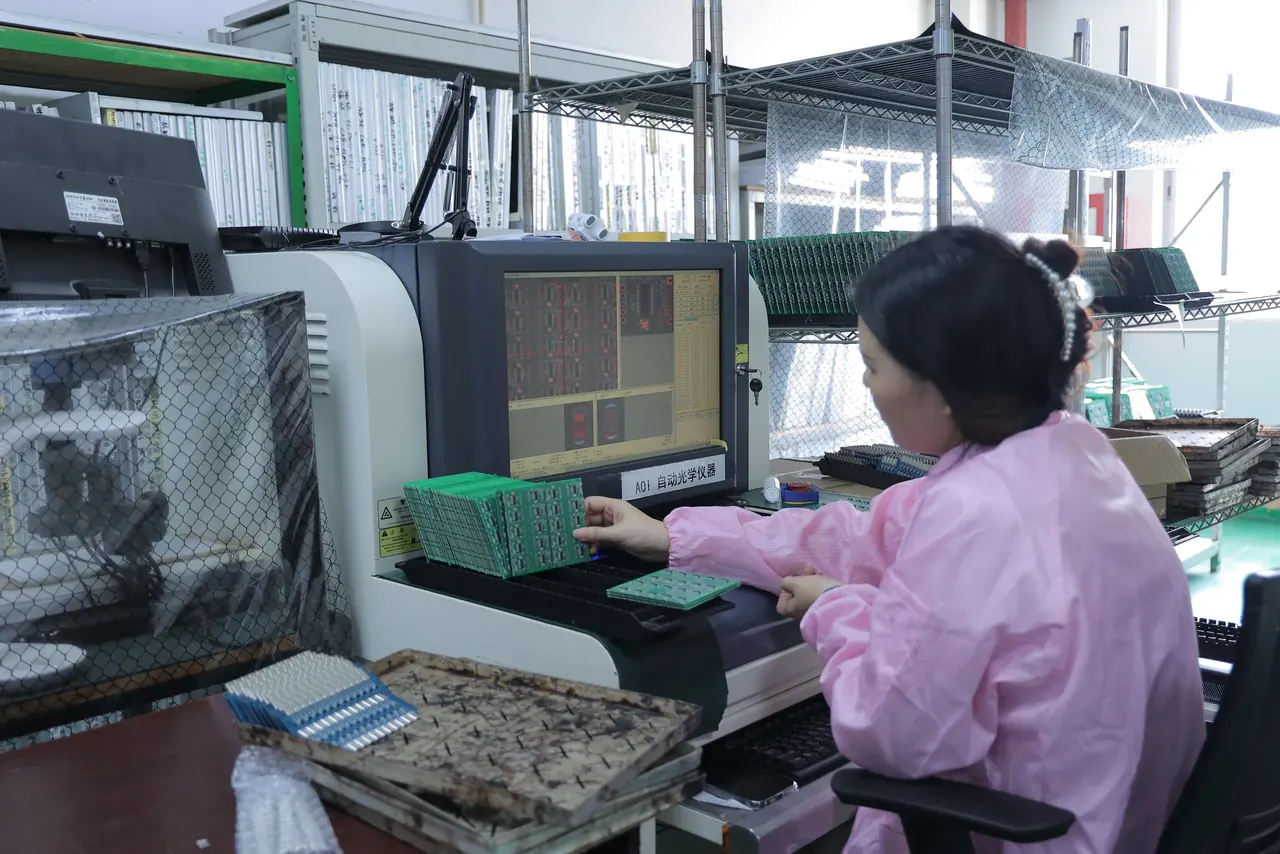
Cameras photograph the board and software compares the image with a reference. After placement it finds missing, shifted, rotated or wrong parts; after reflow it finds solder bridges, lifted leads and many weak joints. It is fast and works on every board.
What it cannot see: anything hidden. Joints under a BGA, under a QFN's central pad or under a shield are not visible. It also cannot tell that a resistor has the wrong value if it looks like the right one, except where the marking is read. Programming errors and internal faults are beyond it. At our factory every board passes SPI and AOI.
X-ray inspection
An X-ray image shows through the part to the joints under it. It is the way to inspect BGAs, QFNs with hidden pads and other packages with hidden connections: bridges, open balls, missing balls and voids (gas bubbles in the solder). Voiding is judged against criteria such as those in IPC-A-610, which the customer may set. X-ray is slower than AOI, so it is used on first articles, on samples from a batch, or on every board if the design is critical. It shows the joint's shape, not its electrical behaviour.
Visual and microscope inspection
A person with a magnifier or microscope checks things automatic systems do not: polarity of unmarked parts, damage, cleanliness, lead trimming. IPC-A-610 is the standard that defines what an acceptable assembled board looks like, in classes for increasing demands, and many contracts name it.
First-article inspection
The first board of a run is built and checked against the BOM and the drawings before the rest are made: polarity, positions, joints, and settings. It is a cheap insurance against a systematic error, such as a wrong part in a feeder.
Test
Flying probe test
Moving probes touch test points and pads on a finished board, one pair at a time, and measure resistance, capacitance or diode behaviour, and check for shorts and opens. No fixture is needed, so it suits prototypes and small runs. It is slow and tests only what the probes can reach. The same method is used on bare boards for continuity.
In-circuit test (ICT)
A fixture with many spring-loaded pins (a bed of nails) presses against test points on the board, and a tester measures each component in place: whether each part is present, has the right value and is soldered. It is fast and finds manufacturing faults precisely, so it is suited to larger runs. The fixture costs money and time to build, and the board needs accessible test points: a pad or via for each net you want to measure.
The drawing shows the two ways a board is probed, with moving probes and with a fixture of pins. It is drawn on a bare board; on an assembled board they work the same way.
- A probe tip touching a pad.
- The probe arm moves from point to point.
- The spring pins of a fixture touch all test points at once.
- The fixture plate holds the pins.
Boundary scan
Parts that support the JTAG boundary scan standard (IEEE 1149.1) can test the connections between them through a few pins, with no probing. It finds opens and shorts under BGAs where no probe reaches. It needs those parts in the design.
Functional test (FCT)
The board is powered and operated as it will be used: inputs are driven, outputs are measured, firmware is run, interfaces are exercised, loads are applied. This tests the whole circuit, including things no component-level test can find: a wrong value in a feedback network that is within the part's marking, a firmware fault, an analogue circuit that is out of tolerance.
A functional test is your test. The factory does not know what the board should do. To have one done, you provide:
- a procedure: what to connect, what to apply, what to read, what is a pass,
- the firmware or test firmware,
- a fixture or the details to build one (or a way to connect cables),
- and the pass and fail limits.
The factory can then build the fixture and run the test on every board. ICT, functional test and programming are among our services.
Burn-in
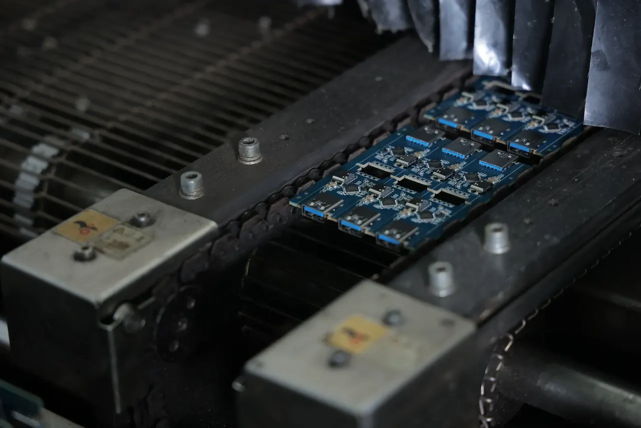
Boards are powered, often warm, for hours or days, to make early failures show up in the factory and not at your customer. It finds parts with latent defects and marginal joints that fail under stress. It takes time and equipment, and is usually applied to a sample or to boards for demanding uses. We run burn-in on samples, at room temperature and at high temperature.
What each finds
| Method | Finds | Misses |
|---|---|---|
| SPI | Wrong paste volume and position | Everything after printing |
| AOI | Missing, shifted, rotated parts; visible solder faults | Hidden joints, wrong values, circuit faults |
| X-ray | Hidden joint faults, voids | Electrical behaviour |
| Flying probe | Opens, shorts, wrong values at reachable points | Hidden nets, circuit function |
| ICT | Faults in manufacturing at the part level | Whether the whole circuit works |
| Functional test | Whether the board does its job in the tested conditions | Faults in conditions not tested |
| Burn-in | Early life failures | Faults that appear later |
Three of these methods side by side show why each sees what it sees.
- Optical: the camera sees the surface. The joints under the part are hidden.
- X-ray: the beam goes through the part, so hidden joints and voids show.
- Probes: needles touch test points and measure at the places they reach.
How to choose
- Prototype: AOI plus your own bench test on the first board is often enough. You are finding design errors, which no factory test finds.
- Small series: add a functional test with a simple fixture, and X-ray for BGAs.
- Volume: use SPI, AOI, ICT or functional test, and sampling X-ray.
- Critical or hard to repair products: add burn-in, stricter inspection class, and records for each board.
Say the acceptance class you need (for example IPC-A-610 class 2 or 3) in the order.
How this shows up when you order here
Our factory runs SPI and AOI on every board, a first-article inspection, and offers ICT, functional test, programming and burn-in. The tests and inspection options in force are on the capabilities page. The 25 checks at upload are a different thing: they check the files, before you pay, and not the assembled board. The check can show that your files are complete, consistent and buildable. It cannot show that your circuit works; only a test with your procedure can show that, and it is yours to specify. An engineer confirms every order. See also How boards are assembled.